Keybaord
i recently got the imputus to rework this project! the handywork was sitting on my shelf and i wanted it to be used rather than thrown away.
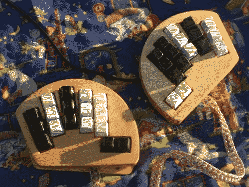
typing on a keyboard is a bit of good fun :3
writing code is a way that i have fun and find joy
construction
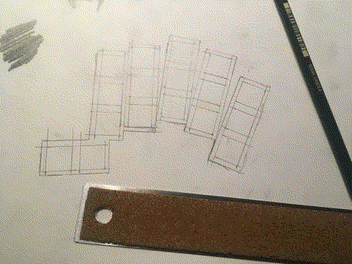
This is designed for the cherry MX switch. I figyred they be the most avalible. The holes are 14x14mm and 5.05mm apart. thats the MX standard.
Made a stencil for the holes.
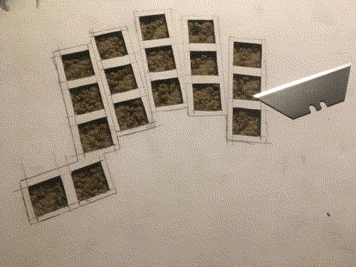
Then worked on the full blue print.
134.4KiB PNG file, 300dpi, black and white indexed|blueprint.png

use this eqation to get it to print at size if printing at 100% is off.
100    ?
--- = ---
 X     15
X is the length of the scale line on the blueprint in cm.
Move the equation around to figure out the new scale '?' to print with.
100*15/x = ?
Made copies of the blueprint onto cardstock paper with a inkjet printer.
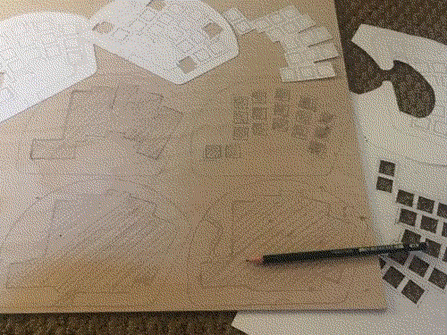
Used those stencils to mark the layers onto 18inch or 2mm thick plywood.
Cut everthing out with this copping saw. it was my great grandpa's.
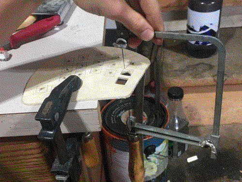
Had a small set of files. These were helpful in making the holes the corect size. made sure the switches fit as i went.
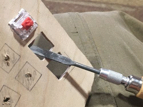
Glued the layers together like this with a decent amount of sucsess. the final product was a bit wobly around where the clamps pinched. next time i need to..
- add a sinlge layer
- place a weight on the layer (flat piece of wood)
- wait for it to set
- the reapet for 4 layers
- clamp multiple layers together with londer pieces of wood

because the outside layers were not all flush, i used this belt sander to make them flush. made it very easy.
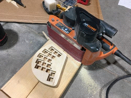
i was lazy and used this to sand up to 220 grit
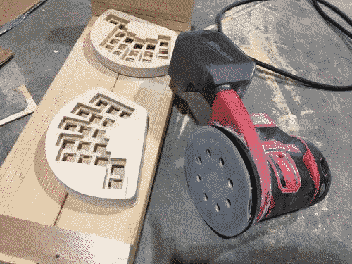
used a piece of 400 grit paper after that for a smooth finish. feals real nice :)
didn't get pictures but i finished it with tung oil.
- mixture 50:50 pure tung oil and mineral spirits
- sploch on well with a rag
- wait 1hr for soak
- wipe off exsess
- wait 12 hours
- do a second coat
- took around 48hr for it to fully dry
end result is very nice.

heres the circutry.
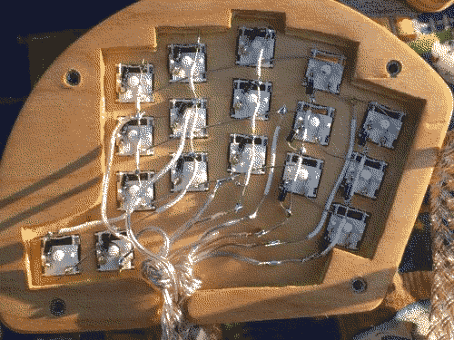
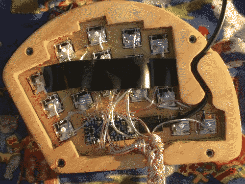

The two hands are conected by this braded cable made from 5 lengths of speaker wire.
uses a 4x10 matrix to read all the keys
curent selector
     ->   ----[ ]-[ ]-[ ]-[ ]-[ ]----------[ ]-[ ]-[ ]-[ ]-[ ]
     ->   ----[ ]-[ ]-[ ]-[ ]-[ ]----------[ ]-[ ]-[ ]-[ ]-[ ]
     ->   ----[ ]-[ ]-[ ]-[ ]-[ ]----------[ ]-[ ]-[ ]-[ ]-[ ]
     ->   -----|---|---|--[ ]-[ ]----------[ ]-[ ]  |   |   |
               |   |   |   |   |            |   |   |   |   |
               v   v   v   v   v            v   v   v   v   v
     read curent
this is to minimise pin usage.
setting a single row low allows you to read which keys are completeing the curct to that row. Because the read pin pull high when not conected low.
there wen't enough pins to read each key indevidually.
diodes are importat to prevent current flowing into other keys than just the row selected, causing key ghosting.
wire each key like this.
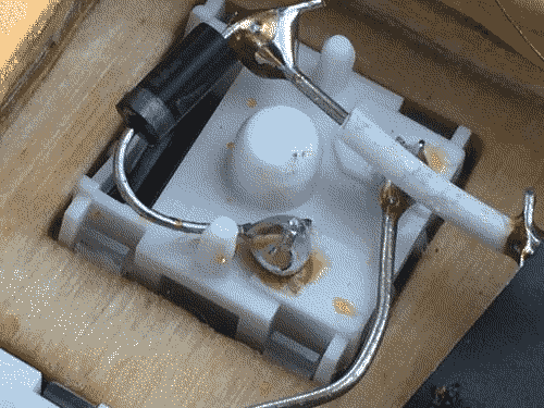
the pin of the switch don't mater.
row goes to on pin.
the other pin goes through a diode then to the colum.
make sure the diode faces into the switch. (shown by witch end the colored ring in on.)
The Microcontroler
ended up useing a Adafirut Itsybity ATMEGA32 micro controller, 16mhz 5V.
the cheap pro micro i used borked itself after reprograming it a couple times.

I was using linux Arduino IDE to program this.
Make sure verbos output is on.
File > Prefrances > Show verbos output during: > upload
Whenever you upload the project, double tap the Itsybitsy's reset button.
this puts it into a diffrent state that i don't fully understand. but it works :|
the code
still working on it :D
i'll report back once its in a groovy state.